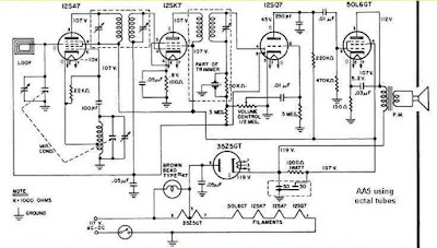
For quite sometime, octal tubes was standard until the minis came out, the 7 pin tubes, then of course the 9 pin tubes. The 6SA7, 6SK7, 6AQ7 and the power amp were replaced by the minis 6BE6,BA6,AV6, an the 50C5. If you have the RCA tube manual, they no longer show the octal version.
Now, if we analyze the circuit, we actually do a hybrid and eliminate the power amp and use an IC amp. Secondly, we will not need the pre amp in the AQ6 since the IC amp is sensitive enough. If not, a tranny will boost the signal. /Thirdly, we do not need a tube diode. A 1n34 will work. I have done this. And the best news is that we won't need the recgifier tube as the RF tubes can work on even 12 volts as well as the IC.
WHAT IT MEANS WE ONLY NEED THE FIRST 2 TUBES! If you have the octals, nice and nostalgic. If none the BE6 and the BA6 will do. 6 olt or 12 volt filament will be ok.
If we need to raise the B+, we can do a voltage doubler. A 1 amp main traffo will do. 12 V will have the advantage of having a higher secondary available.
Now, the rare parts these days are the variable capacitor,the old open type. Next is a pair of IF transformers. There is a DIY instruction in the web. The the 2 coils, the antenna coil and the oscillator coil. They can be home made too. Actually ceramic filters can be used. There are gthousands of IF traffos all over the country, we just don't know where they are. Even some old stores in Raon may have them.
I intend to experiment with the small IFT's used in transistor radios. I have a Zenith AA5 and the antenna coil i modern and is wrapped in a ferrite bar whic can be easily copied.
There is as a last resort a neat trick to make a tuner. Use a rotary switch. since we need 2 ganged switches, the max available is a 6 position double pole SW. We can "channelize" 6 favorite MW stations. Each position chooses a capacitor for the antenna and the osc coil. Parallel to the capacitor is a trimmer. So, the stations are pre-set. If we wan 12 channels, we just externally gang a Single pole, 12 throw rotary SW.
Popular posts from this blog
The problem with the Regen radio was that it was fidgety and lacked selectivity. The next type of tube radio then was called the TRF for Tuned radio frequency. The idea was a series of amplifiers each with a tuning coil. There were just too many tuners! But it can fine tune to a station. It was still figedty to the taste and something has to be developed to make a USER FRIENDLY radio. Armstgrong went back to the drawing board. He knew the principle that frequencies can be MIXED. His goal was go reduce the number of tuning condensers. Finally, he invented the SUPERHETERODYNE radio when a local oscillator is mixed with the incoming signal. The tuning capacitors of the antenna coil and the oscillator coil were ganged. The differential frequency was kept constant at 455 Khz. The next amplifier as tightly tuned to 455 Khz. Till today, this principle is still used. Superhets spread all over the world and in the U.S.A., the most common was a five tube set up. It was called the All American...

Comments
Post a Comment